



You cannot remove layer lines completely on an FDM printer, but you can make them far less visible. Even, regular 3D print layer lines are inevitable part of 3D printing and they do respond to slicer changes such as layer height, orientation and outer-wall speed. Uneven or repeating bands point to a hardware or extrusion fault that you must fix first.
These visible ridges on the surface of your prints are an inevitable part of FDM printing affecting both quality and appearance. Fortunately, there are several techniques you can use to reduce layer lines in 3D prints and achieve a smoother, more professional finish.
This guide is for FDM users, makers and engineers who want smoother parts without wasting filament. It covers three stages: diagnosing the type of line you have, fixing it during printing, and smoothing it after printing. I’ll also explain when a smooth surface is not worth chasing, such as on functional parts with tight fits.
What are 3D print layer lines, and which ones are normal?
3D printing layer lines are the small horizontal ridges left when an FDM printer builds a part one layer at a time. Thin, evenly spaced lines are a normal result of the process. Thick, uneven or repeating bands are a defect.
FDM (fused deposition modelling, also called FFF or fused filament fabrication) is classed as “material extrusion” in the ISO/ASTM 52900 terminology standard. The nozzle lays down a rounded bead of plastic. When beads stack, each one leaves a small groove at its edge. On curved or sloped faces, the layers also form a “staircase”, which is more visible than on straight walls.
Here is a quick way to sort what you see:
- Even lines across the whole part: normal. Reduce them with slicer settings and orientation.
- Bands that repeat at the same height interval: often a Z-axis issue (Z-banding).
- Random thick and thin layers: usually an extrusion or temperature problem.
- A vertical line of blobs or a seam: the Z-seam, where each layer starts and ends.
- Layers that step sideways: a layer shift, caused by belts, pulleys or collisions.
How do you diagnose uneven layer lines?
Diagnose uneven 3D printer layer lines by checking whether the pattern repeats, where it appears, and whether it follows the seam. Then check motion, then extrusion, and change only one setting at a time.
Start with a simple test cube or a tall cylinder. Look at it under side light, which shows ridges clearly. Ask three questions:
- Does the pattern repeat at regular heights? If yes, suspect the Z-axis leadscrew, coupler or gantry.
- Is it worse on one side of the part? If yes, suspect cooling, a draught or a loose belt on that axis.
- Is it random? If yes, suspect filament diameter, moisture, temperature swings or a partly clogged nozzle.
Change one variable, print the same test, and compare. When I started, my idea of slicing was simply to import a file and press slice. I did not know which settings controlled surface quality, and I learned them slowly by trial and error. Testing one change at a time is the habit that finally made my results repeatable.
13 ways to reduce layer lines in 3D printing
The most effective ways to reduce layer lines in 3D printing users see are a smaller layer height, the right orientation, stable temperatures and consistent extrusion. Hardware checks and post-processing then remove what is left.
The first ten methods act before or during the print. The last three are upgrades and finishing steps.
1. Reduce layer height
Layer height sets the vertical resolution of a print. A smaller layer height makes each step shorter, so lines become less visible.
On most 0.4 mm nozzles, 0.2 mm is the standard layer height. Dropping to 0.12 mm or 0.08 mm makes lines much finer. The trade-off is time: halving the layer height roughly doubles the number of layers and the print time.
I’ve found that going below 0.12 mm on a Prusa MK3S+ for detailed prints like miniatures gives excellent results, though it nearly doubles the print time compared to standard settings. For functional parts where looks matter less, I still use 0.2 mm to balance quality and speed.
2. Match layer height to nozzle diameter
Layer height controls detail in the Z direction, while nozzle diameter controls detail in the X–Y plane. Keep layer height at or below 75–80% of the nozzle diameter.
For a 0.4 mm nozzle, that means a maximum of about 0.32 mm. For a 0.6 mm nozzle, about 0.48 mm. Going higher causes poor layer bonding and rough walls. If you want very fine layers and fine wall detail, a 0.25 mm nozzle helps, but it prints slowly and clogs more easily.
From my experience with Creality and Anycubic printers, following this rule helped me avoid flow problems that make lines worse, such as under-extrusion on fine details. It is the first setting I check on any new profile.
3. Tune printing temperature with a temperature tower
The right nozzle temperature gives a consistent bead that bonds well and does not sag. Too hot, and layers bulge; too cold, and they look rough and under-filled.
Start at the filament maker’s recommended temperature. Then print a temperature tower, which steps the temperature by 5 °C at each level. OrcaSlicer, PrusaSlicer and Cura all include calibration tests or plugins for this. Pick the level with the cleanest walls and the best overhangs.
Repeat the test for each new filament brand, and ideally each new spool type. Two PLA spools from different brands can need temperatures 10–15 °C apart.
4. Keep temperatures stable
Temperature swings in the nozzle, bed or room make the plastic expand and shrink unevenly, which shows up as irregular lines.
PLA tolerates small swings well. ABS, ASA, nylon and PETG react much more. Tune your hotend’s PID settings so its temperature holds steady, and keep the printer away from fans, windows and air-conditioning vents.
I once struggled with inconsistent layers when printing PETG parts for an outdoor project. After checking many settings, I found the printer sat near an air-conditioning vent. Moving it to a stable spot and adding a simple cardboard enclosure improved the results dramatically. Even a basic enclosure helps if you do not have a heated chamber.
You can buy an enclosure from your printer’s maker or from third-party brands (affiliate links):
|
Enclosure |
Where to buy |
|
Creality Official
3D Printer Enclosure |
|
|
Comgrow Large 3D Printer Enclosure |
5. Use dry, high-quality filament
Filament with a steady diameter and low moisture extrudes evenly. Cheap or wet filament causes random thick and thin layers.
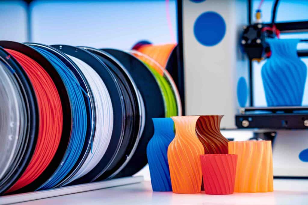
Good filament holds a diameter tolerance of about ±0.02–0.03 mm. Wet filament pops and hisses at the nozzle, leaving bubbles and rough bands. Dry nylon, PETG and TPU before printing, and store spools in sealed boxes with desiccant. Our guide on why moisture is the silent killer in 3D printing explains drying times and storage in detail.
Below are popular PLA brands to consider (affiliate links):
|
Brand |
In India |
Outside India |
|
Polymaker PolyTerra
PLA |
||
|
Creality Premium PLA |
||
|
SUNLU PLA+ |
||
|
eSUN Super Tough PLA |
6. Choose the right print orientation
Orientation decides which surfaces show stair-stepping. Place curved and detailed faces so they run vertically along the Z-axis, where layer height sets the resolution.
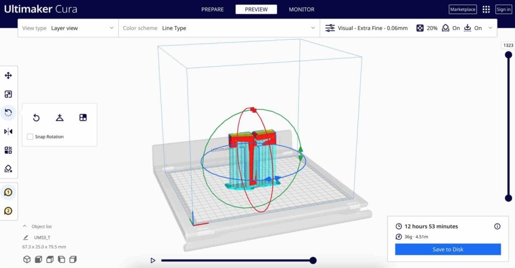
A dome printed upright shows clear steps near its top, where the slope is shallow. The same dome printed on its side shows smooth curves but needs supports. Rotating a part 30–45° can spread layer lines more evenly across curves.
Orientation also affects strength. FDM parts are weakest between layers, so a load that pulls layers apart can snap a part. For functional parts, put strength first and appearance second.
7. Fix over-extrusion and under-extrusion
Over-extrusion pushes out too much plastic and makes layers bulge. Under-extrusion leaves gaps and weak, rough walls. Both make layer lines more visible.
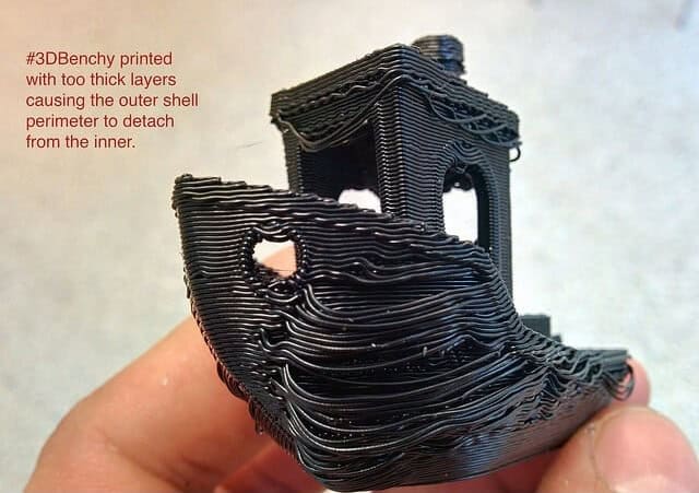
Calibrate extruder steps (e-steps or rotation distance), then run a flow-rate test in your slicer. Lower the temperature slightly if the walls look shiny and bulged. Check that the extrusion multiplier was not left high from a previous filament.
Once, I forgot to reset the flow rate after switching from a translucent filament to an opaque one. The translucent filament needed a 105% flow rate, but the opaque one needed only around 95%. The result looked melted, with bulging layers. Since then, I keep a checklist in my slicer profiles so I set the flow for each material.
8. Check for mechanical issues
Loose belts, worn wheels, a bent leadscrew or a wobbly frame cause bands, ripples and shifted layers that no slicer setting can fix.
Use this checklist before you touch any settings:
- Belt tension: loose X or Y belts cause wobble and ghosting.
- Z-axis movement: a bent leadscrew or loose coupler creates bands at regular intervals.
- Smooth motion: move the print head by hand and feel for binding.
- Frame rigidity: tighten frame bolts and place the printer on a heavy, stable surface.
- Eccentric nuts and wheels: worn or loose V-wheels allow play in the gantry.
- Stepper motor mounts: loose mounts pass vibration into the print.
A rubber or foam damping mat under the printer also reduces vibration-related marks.
9. Slow the outer walls and lower acceleration
Printing outer walls more slowly than inner walls gives a cleaner surface and more even layers.
Fast printers in 2026 can move at 300–500 mm/s, but outer walls still look best at a fraction of that. Many users set outer walls to about half the inner-wall speed. Turn on input shaping if your firmware supports it. It reduces ringing (ghosting) at high speed, which often gets mistaken for layer lines.
10. Control the Z-seam
The Z-seam is where each layer starts and stops. A badly placed seam creates a vertical scar that makes surface lines look worse.
Most slicers let you set the seam to “aligned”, “rear”, “random” or a painted position. Hide it on a sharp corner or the back of the part. Turn on wipe and retraction tuning to reduce blobs at the seam.
11. Use adaptive layer height
Adaptive layer height varies layer thickness through the print. It uses thin layers on curves and thicker layers on straight walls.
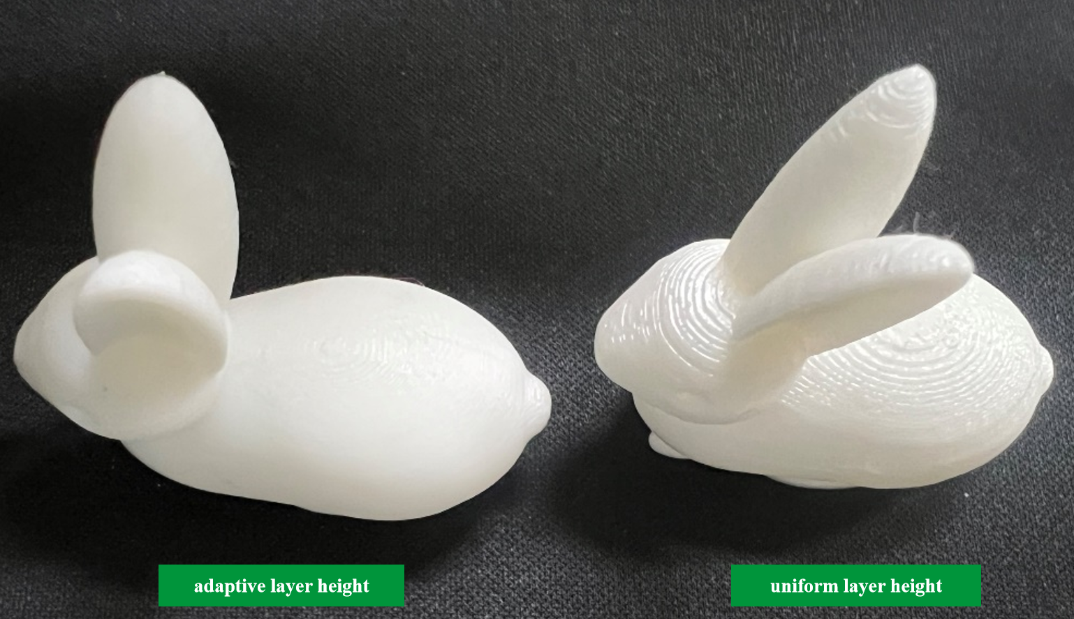
PrusaSlicer, OrcaSlicer and Cura all offer this feature. It might use 0.08 mm layers on a curved head and 0.2 mm layers on a straight base.
I’ve used adaptive layer height in my PrusaSlicer profiles for complex models with both detailed and simple areas. A dragon figurine that took 12 hours at a uniform 0.1 mm layer height took only 7 hours with adaptive layers, and the detailed areas still looked excellent.
12. Turn on arc fitting
Arc fitting replaces many short straight moves with true arcs in the G-code. It gives smoother curves in the X–Y plane and fewer pauses at each tiny segment.
The ArcWelder plugin started this for Cura and OctoPrint users. OrcaSlicer and PrusaSlicer now include arc fitting as a built-in option. Your firmware must support G2/G3 arc commands for it to work. Arc fitting improves curved walls, but it does not change the height of each layer.
13. Upgrade to dual Z-axis or linear rails
Dual Z-axis leadscrews and linear rails reduce wobble and play in the gantry. This removes many of the regular bands seen on older budget printers.
A dual Z setup lifts both ends of the gantry, so one side cannot sag. Linear rails replace plastic V-wheels with steel rails and bearings for tighter, smoother motion. Most new printers in 2026, including CoreXY machines, already ship with these parts. On an older bed-slinger, they are worthwhile upgrades if you print often.
Which fix matches which surface defect?
Match the fix to the symptom before you sand anything. Cosmetic finishing cannot hide a mechanical fault for long.
The table below links common symptoms to their likely causes and first checks.
|
Symptom |
Likely cause |
First check |
Fix during printing? |
|
Even, fine lines
everywhere |
Normal FDM layering |
Layer height and orientation |
Yes |
|
Bands at regular heights |
Z-axis wobble or binding |
Leadscrew, coupler, Z wheels |
Yes, after repair |
|
Random thick and thin layers |
Extrusion, moisture or temperature swings |
Filament dryness, PID tune, flow test |
Yes |
|
Sideways step in layers |
Layer shift |
Belt tension, pulleys, nozzle collisions |
Yes, after repair |
|
Vertical line of blobs |
Z-seam |
Seam position, retraction, wipe |
Yes |
|
Ripples near corners |
Ringing (ghosting) |
Speed, acceleration, input shaping |
Yes |
How do you smooth layer lines after printing?
Post-processing removes the lines that remain after printing. Sanding, filler primer and vapour smoothing are the main options, and each one changes dimensions slightly.
If you are searching for how to get rid of layer lines in 3D printing settings cannot fix, this is the stage to use. Follow a test-first order: fix defects, sand, fill, then paint or polish.
- Sanding: start at 220 grit to knock down ridges, then move through 400, 800 and finally 2000 grit. Wet-sand the finer grits to stop PLA from softening with heat. A polishing compound gives a final shine on display pieces.
- Filler primer: spray a filler primer, let it dry, then sand. Repeat two or three times. This fills grooves without removing much plastic.
- Epoxy coatings: brush-on epoxy fills deep lines and gives a glossy shell. It also adds thickness, so avoid it on mating faces.
- Vapour smoothing: acetone vapour smooths ABS and ASA. It does not work on PLA. Acetone is highly flammable and its vapour is harmful, so follow the safety data sheet, use good ventilation, and never heat acetone near a flame. (link the acetone SDS from your supplier before publishing)
Personally, I keep a small sanding kit with grits from 220 to 2000 for smoothing models after printing. Starting at 220 and finishing at 2000 gives an almost glass-like finish on PLA prints.
Every finishing step removes or adds material. On a 0.1 mm fit, that can turn a snap fit into a part that will not assemble. Check critical dimensions with a calliper after finishing. For more tricks, see our guide to choosing the best free slicer for 3D printing, since modern slicers now hold many of the settings above.
When should you not chase a perfect surface?
Do not chase a perfect surface on functional parts, jigs or fit-test prototypes. Smoothness adds time and often hurts dimensional accuracy.
For a bracket, a jig or an enclosure fit check, even layer lines do no harm. Spend your time on strength, orientation and tolerances instead. Heavy sanding or coatings can also remove fine features and change hole sizes.
If you need a smooth surface straight off the printer, FDM may be the wrong process. Resin printing (SLA, DLP or MSLA) prints layers of 25–100 µm and leaves lines that are almost invisible. Our comparison of FDM vs SLA vs SLS explains when each process makes sense. For show models and customer samples, outsourcing a resin print often costs less time than hours of sanding.
A sensible next step: print one test cube, sort its lines using the table above, and fix the biggest cause first. Then move to slicer changes, and keep finishing for parts that need it.
Tricks to Hide Layer Lines
You can also use a variety of tricks to conceal layer lines in 3D prints. If you're interested in learning more about these techniques, check out our dedicated article on useful tricks to hide layer lines in 3D prints.
Conclusion
You must have understood by now that completely eliminating layer lines is next to impossible for now, and at least in desktop FDM printing. But you can certainly follow good printing practices to reduce layer lines in 3D prints. prominent and visible layer lines. In case you are also facing other issues, you can check out our detailed articles on Common Problems in 3D Printing & How to Resolve Them - Part I and Common Problems in 3D Printing - Part II and get better at 3D printing.
Try out the above mentioned ways and let us know which ones worked for you and now you follow them rigorously.
FAQs: layer lines in FDM prints
Can you print without any layer lines on an FDM printer?
No FDM printer can print without layer lines, because the process builds parts from stacked beads of plastic. Fine layer heights, good orientation and stable extrusion make the lines very faint. For a truly smooth surface, FDM parts need sanding, filler primer or vapour smoothing. Resin printers produce much finer layers and are the better choice when surface finish matters most.
Does a smaller nozzle reduce layer lines?
A smaller nozzle improves detail in the X–Y plane, such as sharp edges and small text. It does not reduce the height of each layer on its own. Layer lines depend mainly on layer height. A 0.25 mm nozzle does allow thinner layers, around 0.05–0.15 mm, but print time rises sharply and clogs become more likely with filled filaments.
Why do layer lines look worse on PETG than on PLA?
PETG is glossy, so light picks out every ridge on its surface. It also strings more and is more sensitive to temperature changes and cooling. Lower print speed on outer walls, tune the PETG temperature with a tower, and keep the printer away from draughts. A matte PLA hides layer lines better than glossy PETG or silk PLA.
Does ironing remove layer lines?
Ironing smooths only the top flat surfaces of a print. The hot nozzle passes over the top layer again with very little flow, melting and flattening it. Ironing does not affect side walls, where most layer lines appear. It also adds print time, so use it for flat lids, badges and nameplates rather than for curved or tall parts.
How long does it take to sand a 3D print smooth?
Sanding time depends on part size, layer height and the finish you want. A small PLA figure printed at 0.12 mm may take 30–60 minutes to reach a paint-ready finish. A large part printed at 0.28 mm can take several hours. Printing at a lower layer height usually saves more time than it costs, because there is less material to remove.


