



For most 3D printing jobs, STL is your safest default 3D printing file format; use OBJ when you need colour and texture, STEP when you need engineering precision and editability, and use IGES only if no other options exist. Now, if this answer sounds suspiciously simple, that's because the devil lives in the details, and a single wrong file export setting can scale your part from millimetres to inches, turning a precision bracket into an absurdly oversized block of wasted plastic. If you've ever pulled a print off the bed only to find ugly, faceted surfaces where smooth curves should be, or watched your slicer crash after choking on a 300-megabyte file, you're not alone. These aren't printer problems, they are file format problems. And in an industry where a single failed prototype can cost an MSME in Pune or Mumbai thousands of rupees in wasted material and missed deadlines, understanding your 3D printing file formats isn't optional. It's a bare minimum necessity.
Whether you’re running a service bureau, freelancing as a product designer, or exploring 3D printing as a side hustle, you need to understand when to use which file format and why it is so. In this article, we’ll break down STL, OBJ, STEP, and IGES, and give you the practical knowledge to choose wisely and avoid costly mistakes.
Why Your File Format Choice Matters More Than Your Printer
Your 3D printing file format determines print quality just as much as your hardware does, and it's the half of the equation most operators overlook. You could own the finest industrial Fused Deposition Modelling (FDM) 3D printer on the market, but if your CAD file is wrongly exported, your physical part will faithfully reproduce every flaw, as the printer executes exactly what the data tells it to do. The core challenge in any 3D printing file format workflow is translation: if you are using a parametric software then your CAD model lives as precise mathematical geometry, and when you hit "Export," that geometry gets converted into a format your slicer can understand. Like any translation, something can get lost, sometimes catastrophically.
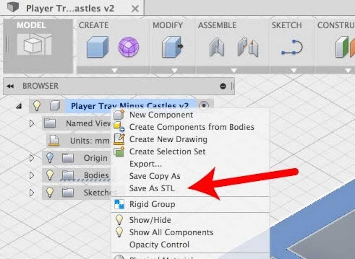
In my experience advising some MSMEs, three costly mistakes repeat themselves constantly.
- First, operators export CAD files with coarse resolution, and curved parts come out looking like low-polygon (surface with a stepped feature) rather than a smooth curve.
- Second, they overcompensate by cranking resolution to the maximum, generating files so massive that their printer’s motherboard stutters mid-print, leaving blobs and zits across the surface.
- Third, they use the wrong 3D printing file format altogether, such as sending a colourless STL file to a full-colour PolyJet printer, or feeding a complex STEP file into a basic desktop slicer that is not built to read it.
Each of these mistakes costs time, rework effort and money. Service bureaus across India report that file-related errors are among the top reasons they reject or reprice orders, since manual labour is needed to repair them.
The Four File Formats Every 3D Printing Professional Must Know
The four most popular 3D printing file formats you’ll encounter in 3D printing are STL, OBJ, STEP, and IGES, and they split into two fundamentally different camps. Mesh formats (STL and OBJ) approximate curves using flat triangles or polygons and mathematical formats (STEP and IGES) store curves as exact equations, so a circle is always a perfect circle, no matter how far you zoom in.
- STL: The Universal Workhorse
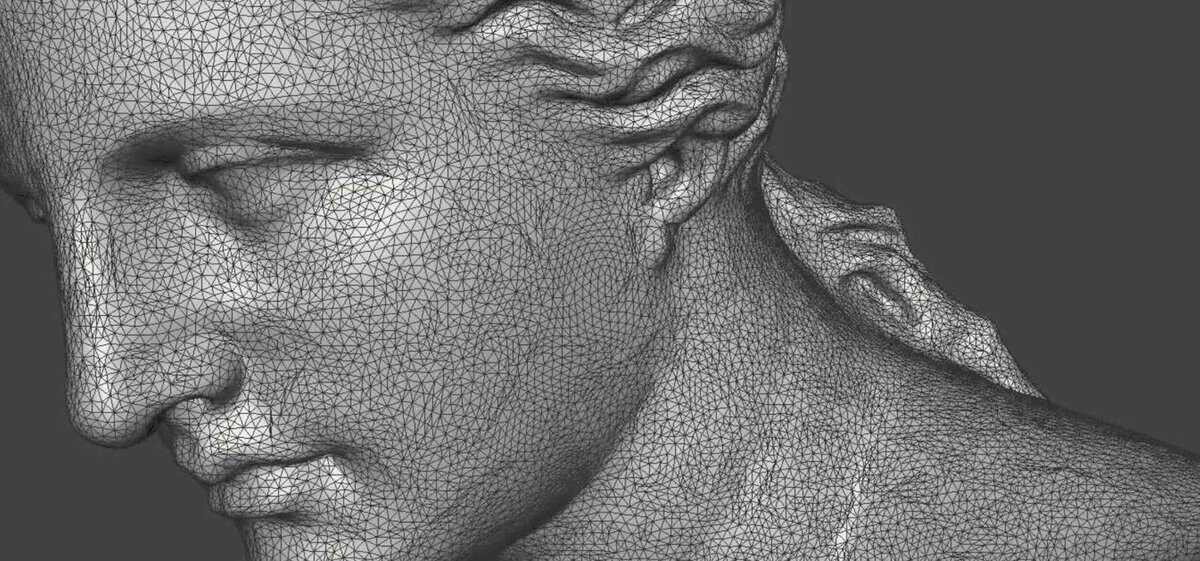
STL (Standard Tessellation Language, sometimes called Stereolithography) is the most widely used 3D printing file format. It is a simple triangle-mesh format that represents your CAD model as a shell of interconnected flat faces. Developed in 1987 by 3D Systems for the very first commercial stereolithography printer, it remains the universal default nearly four decades later. Almost every slicer on the planet, including Cura, PrusaSlicer, ChiTuBox, and Bambu Studio, accepts STL without question.
Each triangle in an STL is defined by three vertex coordinates (X, Y, Z) and a normal vector that tells the printer which side faces outward. That’s it. No colour, no texture, no material data, no units, no assembly information. The format is mathematically primitive but universally compatible and accepted.
This simplicity is both STL’s greatest strength and its most dangerous weakness. Because STL files carry absolutely no unit data, the number “10” in your file could mean 10 millimetres, 10 inches, or 10 metres. If you export from a CAD programme calibrated in inches and your slicer assumes millimetres, your part will print 25.4 times smaller than intended (since 1 inch equals 25.4 mm). I once had a young client from Surat who got a custom jewellery designed by an European freelancer and he designed the model with an 10mm diameter and handed it over to my client but when the client asked his operator to print the file, and the operator printed it without much thought and it got printed with a 10 cm diameter. This single mistake cost the customer a good amount of material and delayed the gold casting process by two days.
STL files come in two types: ASCII (human-readable) and Binary (compressed). The tip is to always export as Binary, as it produces files roughly 80–90% smaller than ASCII for identical geometry and processes significantly faster in your slicer.
- OBJ: When Colour and Texture Matter

OBJ (Wavefront Object) is a polygon-based 3D printing file format that does what STL cannot, as it carries colour, texture, and material data alongside geometry. Originally developed by Wavefront Technologies for computer animation, OBJ isn’t restricted to simple triangles; it can define geometry using quadrilaterals and higher-order polygons, allowing smoother representations with fewer total faces.
OBJ stores UV texture coordinates and material properties through a companion .mtl (Material Template Library) file, which defines surface colours, specularity, transparency, and references to external texture images. This makes OBJ the mandatory format when you’re working with full-colour PolyJet systems, binder jetting, or any multi-material printing technology where visual fidelity is as important as physical shape.
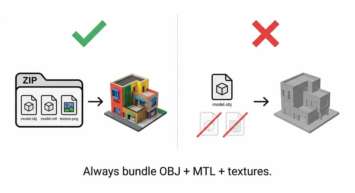
A word of caution: The biggest practical problem with OBJ is its multi-file dependency. Your .obj file references a .mtl file, which references external texture images. If any file gets separated, for example, you send the .obj but forget the .mtl and texture folder, all colour data vanishes. I’ve seen architectural firms lose entire print runs because texture files were missing from the ZIP archive. Always bundle your OBJ, MTL, and texture images together in a single compressed folder before sharing.
Also note that, like STL, OBJ also carries no unit information. It’s inherently ASCII-only (no binary variant), so OBJ files tend to be larger and slower to slice than comparable binary STL files.
- STEP: An Engineer’s Gold Standard
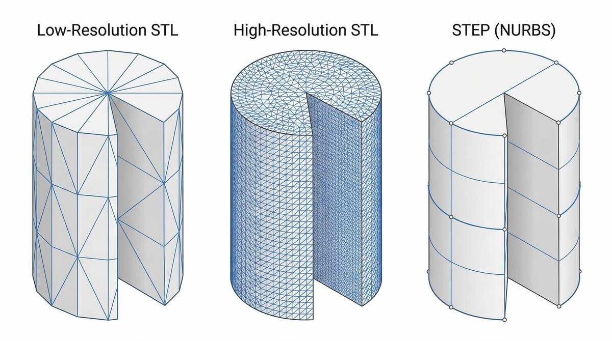
STEP (Standard for the Exchange of Product model data), formally designated as ISO 10303, is the only format among the four we are discussing today that stores your geometry as mathematically exact shapes rather than polygon approximations. It is a true Boundary Representation (B-rep) solid modelling format that defines surfaces using Non-Uniform Rational B-Splines (NURBS), meaning a cylinder isn’t approximated by thousands of flat triangles but is defined as a mathematically perfect cylinder with a specific origin, radius, and extrusion vector.
This mathematical precision makes STEP files dramatically smaller for curved geometry, for example, a smooth cylinder that occupies just 0.007 MB as STEP might balloon to over 2 MB as a high-resolution STL. STEP also stores rich metadata: assembly hierarchies, dimensional units, component colours (in AP214 and AP242 protocols), and even geometric dimensioning and tolerancing (GD&T) data. For engineering workflows where mathematical precision cannot be compromised, such as aerospace components, automotive tooling, and medical implants, STEP is non-negotiable.
But here’s a critical misconception: most consumer slicers cannot directly generate G-code from STEP’s mathematical NURBS. When PrusaSlicer or Bambu Studio imports a STEP file, they silently convert it into a triangulated mesh before slicing. Community testing has shown that these built-in conversion engines are often inferior to the export tools in professional CAD software. For complex curved geometries, a carefully optimised STL exported from your CAD environment will often yield a better print than the slicer’s automatic STEP-to-mesh conversion.
- IGES: The Legacy Format You Should Approach with Caution
IGES (Initial Graphics Exchange Specification) is an outdated 3D printing file format based on surface modelling that stores CAD bodies as a collection of independent mathematical surfaces, surfaces that don’t inherently “know” about their neighbours. First published in 1980 and last updated in 1996, it was groundbreaking for its era but has become increasingly problematic for modern 3D printing workflows.
The core issue is that IGES geometry lacks the topological connectivity needed to form a guaranteed watertight solid, which is the absolute minimum requirement for any 3D printer to print correctly. When you import an IGES file into modern CAD software, you’ll frequently encounter microscopic gaps between surfaces that developed during translation. A slicer that encounters these gaps cannot resolve the volumetric boundary, which means it will either refuse to slice or produce a part with missing layers and structural failures. Industry experts rank IGES as the format of last resort: native format first, then STEP, then, only if nothing else is available, IGES.
Choosing the Right 3D Printing File Format: STL vs OBJ vs STEP vs IGES Comparison
When evaluating STL vs OBJ vs STEP vs IGES, the right format depends on three criteria: file size and processing weight, compatibility with your specific printer technology, and how easily you can edit the file after export. Here’s how the four formats compare across each.
| Criterion | STL | OBJ | STEP | IGES |
| Data Type | Triangle mesh | Polygon mesh + textures | Exact B-rep (NURBS) | Surface model |
| File Size (curved parts) | Large (bloats with resolution) | Moderate to large (ASCII only) | Very compact | Variable, often bloated |
| Colour/Texture | None | Yes (via .mtl) | Yes (AP214+) | Basic RGB only |
| Unit Data | None | None | Yes | Yes |
| Slicer Support | Universal | Most slicers | PrusaSlicer, Bambu Studio, OrcaSlicer | None: must convert first |
| Post-Export Editing | Very difficult (mesh only) | Very difficult (mesh only) | Excellent (reimport into CAD) | Poor (surfaces need stitching) |
Which 3D Printing File Format to use for which 3D Printer?
- FDM/FFF (desktop prototyping): STL works for most use cases, but STEP is also now widely used in FDM/FFF 3D printing.
- SLA/DLP (resin, high-detail): Use high-resolution STL exports (tight tessellation) or STEP for simple geometry.
- Full-colour printing (PolyJet, binder jetting, multi-material): OBJ + .mtl is mandatory.
- Powder-based 3D printing (SLS/MJF/DMLS): STEP is preferred so service bureaus can control tessellation quality.
The Hidden Pitfalls That Ruin Prints
Three specific file-level errors - faceting, unit mismatch, and broken mesh topology - account for the vast majority of preventable print failures.
- The Faceting Trap
Faceting happens when your STL export resolution is too coarse, turning smooth curves into visible flat polygon steps on your printed part. When your CAD software converts perfect mathematical curves into flat triangles during export.
But the instinctive fix, cranking resolution to the maximum will massively increase the file size which most slicers will either not be able to handle or if it does handle it then the print quality will suffer and you might see blobs on the printed part.
- The Scaling Nightmare
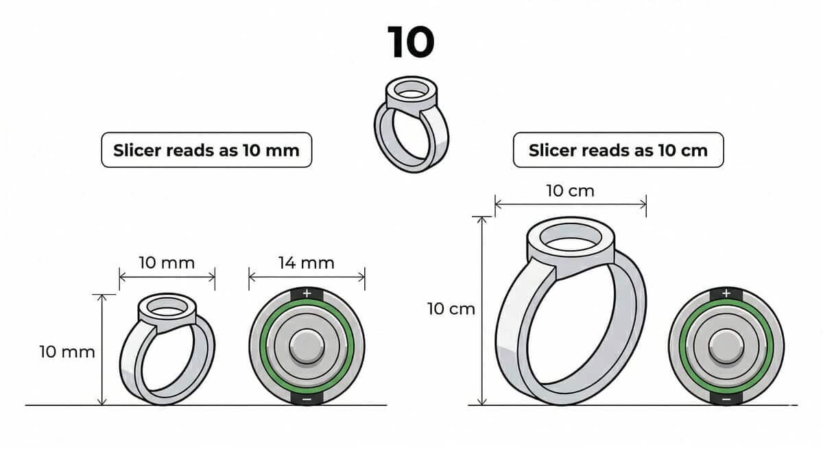
Unit mismatch is another common cause of wildly mis-sized prints. As I mentioned earlier, STL and OBJ files do not contain unit information and so a model designed in inches but imported into a slicer calibrated for millimetres will produce a part scaled down by a factor of 25.4.
Unit mismatch is the most common cause of wildly mis-sized prints. As I mentioned earlier, STL and OBJ files do not unit information and so a model designed in inches but imported into a slicer calibrated for millimetres will produce a part scaled down by a factor of 25.4.
- Non-Manifold Geometry and Inverted Normals
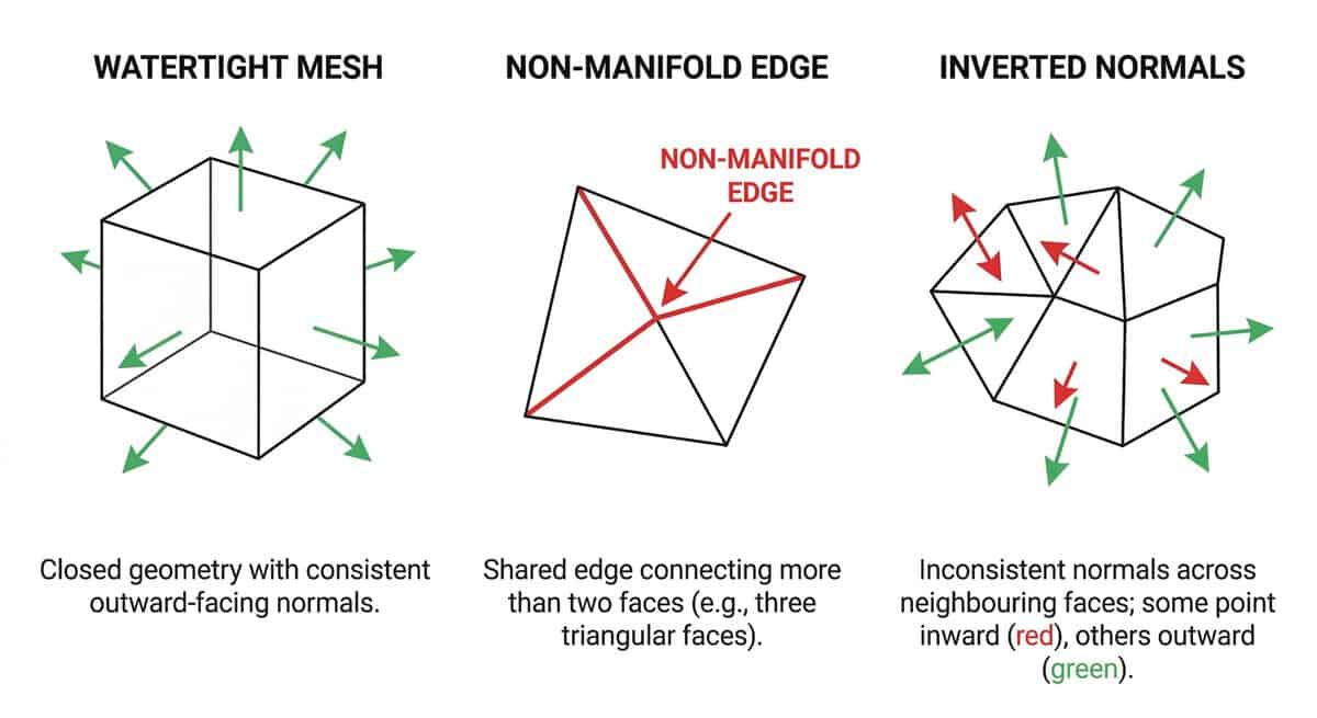
Non-manifold geometry and inverted normals are mesh defects that make your model physically impossible to print. A manifold object is one that can physically exist, a continuous, watertight skin separating inside from outside. Non-manifold geometry occurs when more than two triangles share a single edge, or internal faces bisect the model’s volume. When your slicer encounters this, it cannot determine what’s “inside” the object, resulting in missing walls or failed toolpath generation.
Your Export Playbook: Settings That Actually Work
These are the exact export settings, repair tools, and pre-export checks I recommend to every client and colleague to prevent the failures described above.
STL Export Best Practices
The goal of every STL export is to strike the right balance between surface smoothness and file size; these five settings will get you there.
- Export as Binary, not ASCII. Binary files are dramatically smaller and faster to process.
- Set chordal deviation to 0.1 mm as a starting point. For high-detail SLA or DLP work, tighten this to 0.01–0.05 mm.
- Set angular tolerance to 1–5 degrees. This forces the software to generate denser triangles on tight curves without bloating flat surfaces.
- Keep your final file under 20 MB. If it exceeds this threshold, increase your tolerance values to reduce the triangle count safely.
- In SolidWorks, check two boxes: "Do not translate STL output data to positive space" and "Save all components in a single file" to prevent coordinate shifts and assembly dislocation.
For STEP exports, use AP242 when available (it's the most complete protocol, superseding both AP203 and AP214). Fall back to AP214 if your receiver's software is older, and use AP203 only for maximum backward compatibility.
When Things Go Wrong: Repair Tools That Save the Day
If your STL or OBJ file fails due to non-manifold geometry or mesh errors, dedicated repair tools can often salvage it before printing. For a detailed breakdown of tools like Meshmixer, Netfabb, and Materialise Magics, refer to our complete guide on STL repair tools.
Your Pre-Export Checklist
Five checks, five minutes, and you’ll catch 90% of errors that cause print failures before they ever reach your machine.
- Verify that your model is a single, closed, watertight solid with no overlapping bodies or internal faces.
- Confirm that export units match your slicer's expected units (typically millimetres in India).
- Inspect the exported mesh visually in a slicer preview for faceting, missing faces, or inverted normals.
- For OBJ exports, bundle the .obj, .mtl, and all texture images into a single ZIP file before sharing.
- For IGES files (if you absolutely must use them), run surface diagnostics and stitch all surfaces into a solid body before exporting to STL.
Bringing It All Together
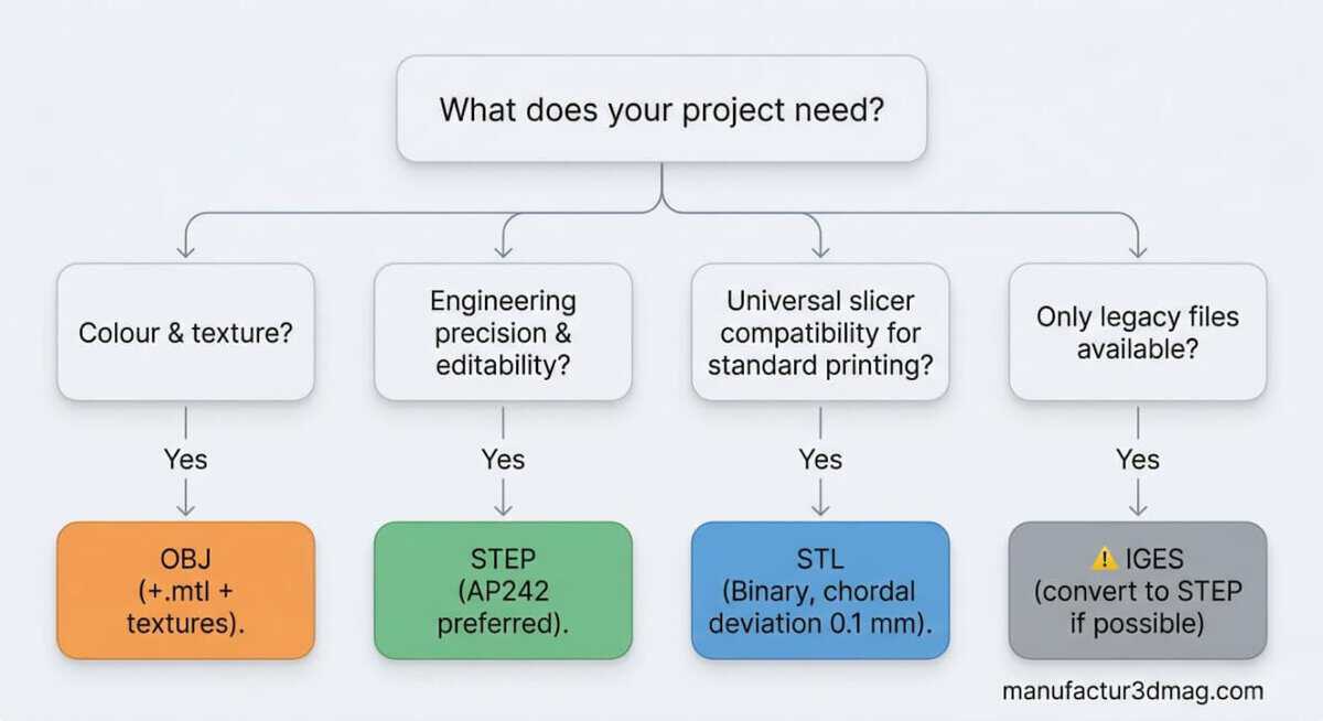
The right 3D printing file format isn’t a matter of preference, especially when comparing STL vs OBJ vs STEP vs IGES; it’s dictated by your workflow stage. Keep STEP as your master engineering file for precision and editability. Export STL at carefully tuned resolution as your final printing format. Use OBJ exclusively when colour and texture data are required. And approach IGES with extreme caution, converting to STEP whenever possible.
India’s 3D printing market is projected to reach several billion dollars within the next decade, with MSMEs driving much of that growth. Whether you’re a service bureau in Pune, a jewellery manufacturer in Surat, or a prototyping startup in Bengaluru, mastering your file format workflow is one of the highest-leverage skills you can develop. It’s the difference between reprints and profits.
We wish you the best of luck refining your workflows, and if you need further guidance on optimising your CAD-to-print pipeline, explore our other articles on slicing strategies, material selection, and post-processing techniques.


